Cricut Venture
Cricut Venture Parts
For the Cricut Venture I was the owner of the cosmetic case parts. This involved heavy interaction with the ID team to ensure good cosmetic appearance, and I helped to define many gaps and steps requirements/testing. In addition to looking good, many of these parts were also functional which required me to be creative and have good knowledge about materials and finishes. For this machine I also designed many of the accessories that were used to improve user experience and facilitate with machine maintanence.

Right End Cap
The Venture end cap was one of the largest ABS plastic injection molded parts I have designed. In order to meet the ID requirements, the outer edge was made with three sliders to avoid draft.
In core side require critical alignment and of the main UX board and status bar light pipe, power plug and USB port. Lifters were used for the attachment hooks in order to attach the case part without visible hardware.
This part utilized a sprue gate in order to allow for easy consistent filling. This also helped prevent part warp and ensured good alignment and gap control to four other case parts.
Due to limited space to the electrical power switch the cosmetic power button was biased towards the case part with conical springs which were able to fully collapse flat.


UX Button Board
The UX button board was the main interaction point for the user. This included a load, play and pause button. There was also an LED status bar to help indicated the state of the machine. I worked closely with an electrical engineer in order to provide details regarding board layout and attachment.
The three buttons were designed with clear ABS and the symbol was laser etched. Under each button was 60A durometer silicone light pipe that helped give even light dispersion, prevent light bleed and provide a soft touch button press.
The button mount is made from POM in order to help the buttons slide easily on the key features which were designed to prevent mis-assembly. For the mount I utilized various pass core features to mount the board and help reduce tooling complexity.
In order to get an evenly dispersed lighting in the status bar I selected clear ABS with 1g/kg titanium fill.


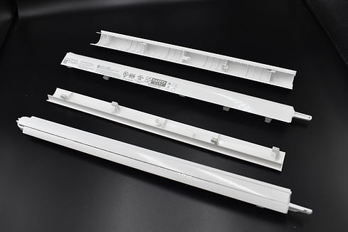
Front and Rear Material Handling
The front and rear material handling plastic parts were long thin parts that were made from a PC/ABS blend in order to help enhance the mechanical properties and wear with PC, but maintain the flexibility of ABS.
The parts also housed two arms that were attached to an internal linkage system. I designed a knurled pin that acted as the pivot point of the arm and performed a tolerance stack to ensure that the pivot location did not cause any binding when the arms opened.
I performed several experiments on the curvature of the rear material handler in order to ensure material flowed across the floor properly without slipping through the drive rollers.
The front material handler incorporated a groove for the manual cut-off accessory to ensure that users could easily perform a straight cut.


Mat Arm Release Button
The Mat arm release button was a sprung button that interacted with a latch in order to release support arms that were used when cutting with a mat. The button also included a light pipe with indicated when the user should press the button.
This assembly used many materials and features similar to the UX button board. One different requirement was that this button was designed to be an easily contained sub-assembly since the button required a heavier spring in order to properly bias it upward.


Left End Cap
The left end cap consisted of three parts that had various snap features formed by lifters or sliders. Once the top and bottom case parts were snapped together the manual cut-off storage pocket could then also be snapped into place.
The portion was design with ribs at 50% of the nominal wall thickness and small recesses were added around attachment bosses in order to prevent sink on the cosmetic surface. Datum posts were added to the part which helped control placement of the case part to ensure good alignment with the mat release button and pinch arm handle
The left upper end cap was another large case part that required critical gap control with a button assembly. I designed the ribs to be 50% of the nominal wall thickness and small recesses were added around the attachment to avoid visible sink marks on the outer cosmetic surface.
I designed the manual cut-off tool storage pocket to have a small silicone pad that could be pressed into place to order to retain the tool.


Left End Cap Support Bracket
The left cap support bracket was designed in order to attach the left end cap to machine and was made from SECC Steel. It also acted as one of the main areas for users to lift the machine.
I designed this part following best sheet metal practices in order to ensure proper clearances, hole to edge positions and radii to prevent sheet metal deformation.
In order to position the case parts properly on the sheet metal hole and slot datum features were used.


Base Parts
Initially the base assembly was designed as single sheet metal piece. Due to some of the limitations on attachment points I took the previous design and broke into several pieces in order to help with assembly. All the base case parts had a MT11000 texture, so it was critical to ensure they had proper draft to release from the molds. Since MT11000 is a rough texture, I also helped to perform various scratch and adhesion testing of the hot foil logo.
Due to the position of the center of gravity of the cutting machine, I designed the length of the front base part to prevent he machine from easily tipping forward.
For the rear case panels I design a honeycomb rib structure to help increase the rigidity. The machine had a roll support accessory which attached to the bottom of the case part. I added small detents on to help indicate to the user when the roll holder was positioned in the correct location.
Both the side case parts were designed attach to the sheet metal end plates, so it was critical for them to be structurally rigid.


Sheet Metal Base
The sheet metal base was made from SPCC Steel and powder coated in order to color match the ABS base case parts.
Since the cutting machine had a vacuum hold down, I designed formed louvers that ensure the material vacuum fan and maintain negative pressure.
I designed an additional form feature which interacted with a locking mechanism on the stand the machine. It was important to design this form feature with large radii to prevent excessive material thinning or tearing.
Countersunk holes and screws were used in order to maintain a flush appearance.

Performance Blade
In order to help increase the blade life for the Cricut Venture when cutting at higher speeds I helped to experiment with different blade geometries in order to improve the life of the blade when cutting on cardstock. This blade had a sharper grind angle with helps reduce wear when cutting through the material.
The blades are made out of German carbide and pressed into a 1045 steel shank that was electropainted white in order to help users identify the blade type.
After working on the performance blade I help lead and review a further DOE on blade geometries to better optimize blade geometry depending on the type of material being cut.


Automatic Cut-Off Tool
The automatic cut-off tool was designed to be able to be clamped into the accessory clamp so that it could be used at the same time as the cutting blade.
The body of the tool was made out of ABS and had a 420 Stainless Steel insert molded into it. Since the tool was not able to clamp on the ground edge of the blade a small PC cap was glued using Loctite 401 which has good compatibility with plastic. The PC end also helped prevent wear on the bottom of the tool as it rubbed across material.
The tool also included a protective cap that was made out of PC. I design the part to require a blind slider which enable me to have a small undercut on the inside of the cap without have a cosmetic opening on the front.
In order for this tool to perform a clean cut and not damage the cosmetic floor it had to fall into a small groove. I performed a very extensive tolerance stack that included 25 dimensions in order to ensure that the tool was capable of falling into the groove.


Manual Cut-Off Tool
The manual cut-off tool was another accessory that came included with the machine so that users could still make a clean cut to material after running the machine. This tool is a PC+PBT blended plastic with a 420 Stainless Steel blade insert. Initially I had selected PC for the body of this plastic, however the notch sensitivity of PC led to cracking and failure of the plastic near the blade. In order to fix the issue, I tested a variety of blended and glass filled polymers with acetic acid to help identify which plastics were had higher internal stress.


Roll Supports
The roll holders were designed to allow user to take advantage of the 12' cutting length of the Cricut Venture.
For this part I had to design a ramped section on the bottom of the tool that allowed them to be installed on the back of the machine when it was sitting on the tabletop. The body was made out ABS plastic, the wheels were made out of POM for low friction and wear characteristics, the pins were made with 304 Stainless Steel, the roll alignment tab our of powder coated SPCC Steel and finally an adhesive backed PET sheet was added to the bottom to help prevent users from scratching their table.
One last feature of the tool was a small cantilever tab that interacted with recesses on the rear base panels in order to indicate the location the roll holder should be installed when using a 13" or 15" wide roll.


Rail Cleaner and Cloth
One of the center staple pieces of the Cricut Venture was the Anodized Aluminum 6061 carriage rail that has polished V-groove for the carriage wheels. In order to ensure good performance and prevent excessive wear to the carriage wheels it was important to have a cleaning accessory. The rail cleaner was a small PP part that I designed. PP was selected so that a fiber cloth could be installed under the rail cleaner and then it could be easily snapped into the upper and lower V-grooves.


Drive Roller Cleaning Brush
When running material through the drive rollers debris would often build up and cause material tracking issues. This brush was designed with nylon bristles to help clean the drive roller without scratching the cosmetic plastics near them.


