Cricut Venture
Cricut Venture Case Parts
For the Cricut Venture I was the owner of the cosmetic case parts. This involved heavy interaction with the ID team to ensure good cosmetic appearance and gap control between parts on the Cricut Venture cutting machine.

End Cap
The end cap was a large cosmetic part made out of ABS. In order to meet the ID requirements, the outer edge was made with three sliders to avoid draft. The Cricut logo was done with hot foil transfer.
End Cap Core
The end cap core required no visible hardware therefor I designed snap features around the exterior that could properly flex over sheet metal attachment points. Other various features required lifters in order to attach the button board and cosmetic power button. I worked with the vendor to select a sprue gate in order to properly fill the part and reduce warp.


Cosmetic Power Button Spring
Due to limited space on the inside of the end cap to the electrical main board, I design a conical spring that could fully collapse to a flat profile.
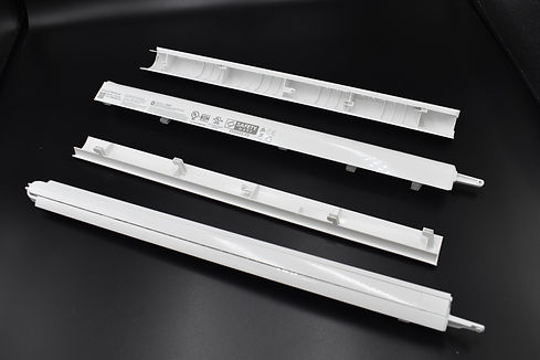
Front and Rear Material Handling
The front and rear material handling plastic parts were long skinny parts that were made from a PC/ABS blend in order to have better wear characteristics than ABS alone. The parts also housed the mat support arm which are used when cutting matted materials on the venture. I designed a knurled pin that also pressed into the parts to act as the arm pivot.


Left Upper End Cap
The left upper end cap was another large case part that required critical gap control with a button assembly. I designed the ribs to be 50% of the nominal wall thickness and small recesses were added around the attachment to avoid visible sink marks on the outer cosmetic surface.
Lower Left End Cap
This was a thin plastic part that I designed to have many small snap windows. The snap windows helped with gap control even if the part was slightly warped along the thin section.


Manual Cut off Pocket
This was a small pocket on the rear of the machine that would snap into the upper and lower left end caps. The pocket has a small silicone pad that could be pressed into place in order to provide good retention for the manual material cut off tool,
Front Base
I performed several calculations to determine the center of gravity of the machine and ensure that the front base designed to help prevent tipping hazards. The lower base section also had a heavier MT11000 texture, so I helped perform adhesion testing.


Rear Base Panels
I designed the rear base panels with a honeycomb ribbing to improve the rigidity or the base structure. At the lower part of the panel there are two slots so that a roll support accessory could be installed. In order to support multiple roll widths, small detents were added so that the user would have a tactile indication of where the roll support should be placed.
Left Base
This is another example of a large ABS part. It was important for this part to be structurally rigid to help support the main sheet metal end plate.


Right Base
This was a smaller base part that also was the main support to the sheet metal end plate. The mall opens interfaced with ribs on the end cap to act as a secure lifting point.